Technical Advisory & Assurance
Technical study · Engineering & Design
CFD modelling in COMSOL to test whether a battery enclosure's ventilation keeps flammable vent gas below safe limits if a cell goes into thermal runaway, and the simplest fix if it doesn't.
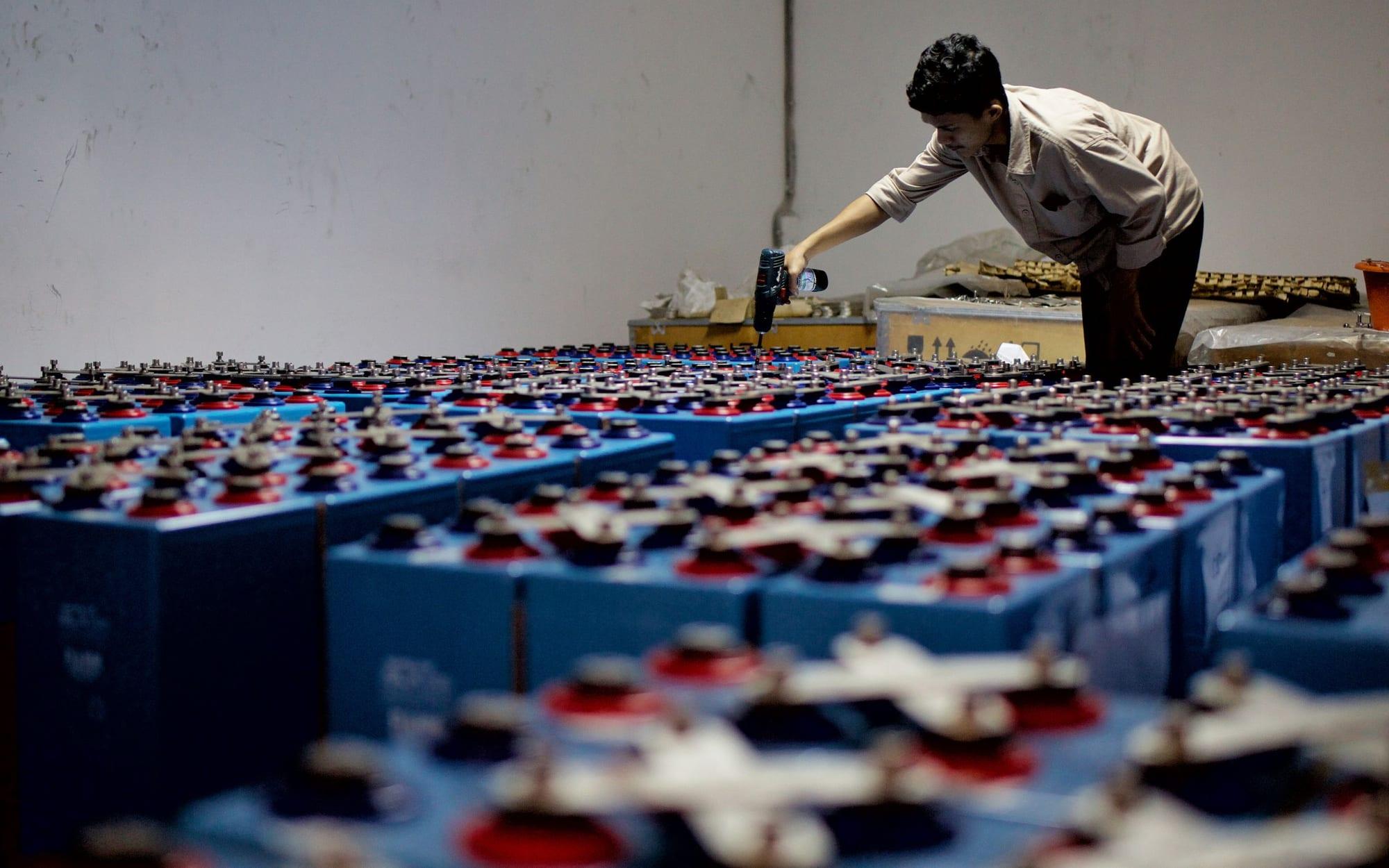
A battery integrator delivering containerised battery systems in Australia came to us after a fire engineer reviewing the design asked whether the enclosure ventilation would keep flammable vent gas below safe limits if a single cell went into thermal runaway. They needed an answer quickly, without an expensive product redesign.
The question they needed answered: If a cell vents, does the ventilation keep gas below 25% of the lower flammability limit (LFL)? If not, what is the simplest change that does?
With the inlet and exhaust on the same wall, fresh air short-circuits straight to the exhaust. Buoyant vent gas forms a layer under the roof, above 25% LFL, in the part of the enclosure furthest from the fan.
Moving the inlet low on the opposite wall sets up a sweeping flow along the ceiling to a high-level exhaust. Gas above 25% LFL is then limited to a small region near the release and at the exhaust itself.
Doubling the fan rate in the original layout helps far less than moving the inlet, and adds cost, noise and auxiliary load for the life of the asset.
Deflagration vent panels are still needed as a second layer of protection. The model shows where gas collects, which sets where the panels go.
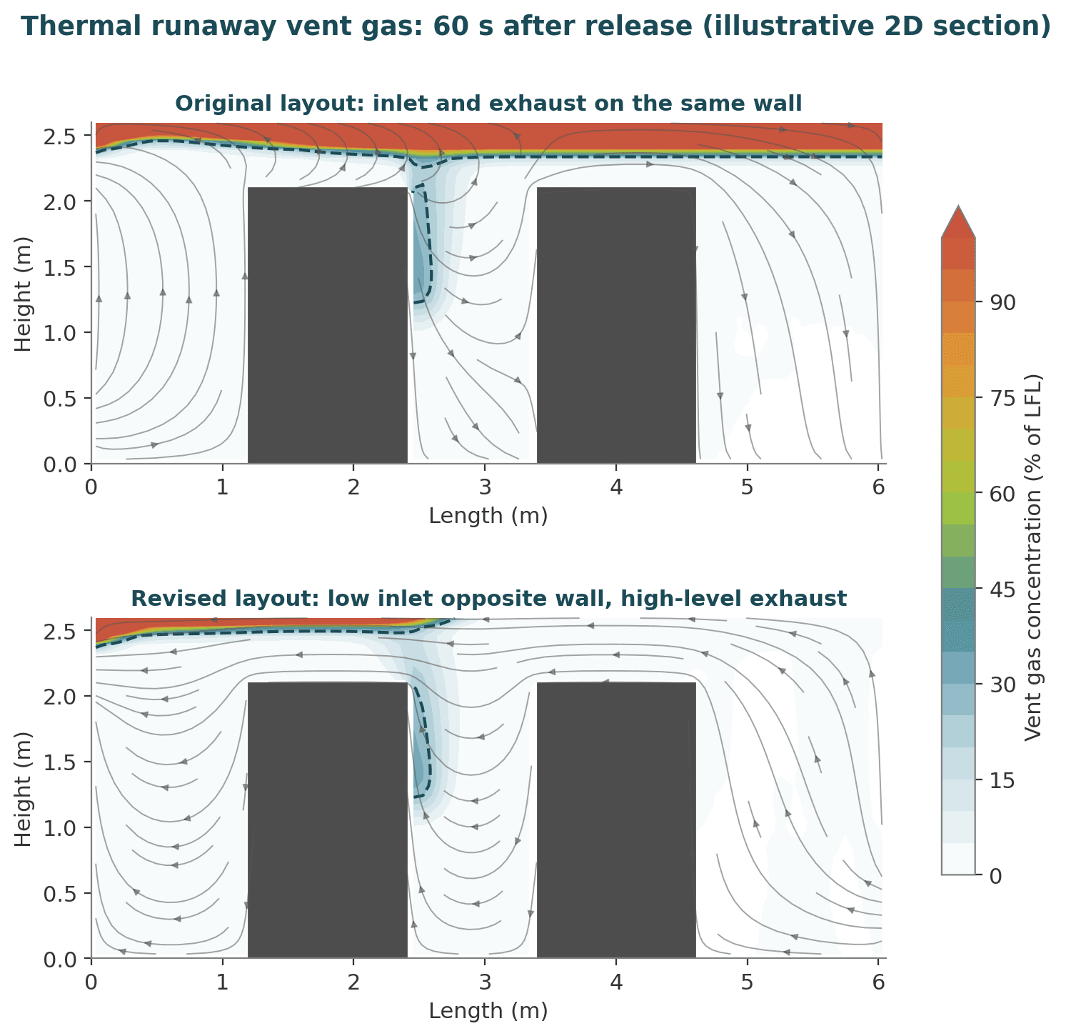
Vent gas composition and release rate based on representative UL 9540A test data for LFP cells. Standards referenced: NFPA 855, NFPA 68 and NFPA 69.
Tell us what you're working on, and one of the people below will get back to you.
Talk directly to


Want to join us? We're always keen to hear from engineers who value strong fundamentals and real delivery experience.
Careers at Amarna